
I purchased a Dorman - OE Solutions - Variable Restrictor Valve (Part No. 902-008). There is an arrow on the part that is suppose to face firewall. There is controversy on which direction the valve is suppose to face. Many people are reporting the the arrow is incorrect. I no longer have my OEM that came off the 2005 Dodge Grand Caravan. Can someone tell me what I should see if I look in the end of the part to signify correct direction? Could this be the reason why my other Caravan is overheating if valve was installed backwards? Thanks.

SAteveGArisssom
Variable Restrictor Valve Flow Direction?
1 reading
SAteveGArisssom
Discussion starter
60 posts
·
Joined 2020
- Add to quote Only show this user
I purchased a Dorman - OE Solutions - Variable Restrictor Valve (Part No. 902-008). There is an arrow on the part that is suppose to face firewall. There is controversy on which direction the valve is suppose to face. Many people are reporting the the arrow is incorrect. I no longer have my OEM that came off the 2005 Dodge Grand Caravan. Can someone tell me what I should see if I look in the end of the part to signify correct direction? Could this be the reason why my other Caravan is overheating if valve was installed backwards? Thanks.
1,227 posts
·
Joined 2015
I'll probably need to see if I can find the old valves I have laying around to give a definitive answer. In a condensed version of my saga regarding replacing this valve long ago, I know that I figured out that the Dorman valve I purchased was configured backwards from the OEM and other manufacturer's replacement valves I went through on my adventure.
Basically, there is a rubber grommet/oriface/seat inside the body of this valve with a spring holding it "closed" against one side of the valve body. Presumably, the coolant flow direction should act to compress the spring to increase flow around this grommet as pressure increases and the grommet/seal is pused back away from the valve body wall.
IIRC, I used a pencil (eraser end) to play around with each valve and prove to myself that the Dorman valve was configured with the spring and valve seat (grommet thing) reversed as regards the arrow direction compared to every other valve I had. Though I like the "fused body" design of the Dorman, this shook my confidence enough that I ended up going with another manufacturer's part instead.
If your Dorman valve is also designed "backwards" then it should go in the opposite direction of the OEM valve; however, I'd be concerned that they might have corrected the issue since then? IIRC, the OEM valve had the arrow installed pointing toward the firewall and the spring compressed in that same direction; however, I need to re-verify this. Would suggest seeing which way your Dorman valve compresses any maybe we can figure it out from there...
This is unlikely to be the reason your van is over-heating... as I understand it, this valve purely serves to assist with getting heat to the rear of the van when the coolant flow/pressure is low...
32,966 posts
·
Joined 2008
The arrow should be in the direction of flow. That should be easy enough to determine. The heat source is from the area of the thermostat and the return goes to the water pump.
I have an OE one here, on my table, from a 2002 DGC 3.3L, Patent # 4800925. I think these control valves were used by other manufacturers as well, like GM.
The arrow points from the thicker end (cap end?) to the thinner end, the same as Dorman per rockauto.com.
Probing about 1 3/4" in from the thicker end and there's a spring loaded valve there that can be easily compressed. It can be pushed in about 1/4" (2" total) before it meets 3 stops on the other side.
What does it do?
More than you wanted to know per:
")
I have an OE one here, on my table, from a 2002 DGC 3.3L, Patent # 4800925. I think these control valves were used by other manufacturers as well, like GM.
The arrow points from the thicker end (cap end?) to the thinner end, the same as Dorman per rockauto.com.
Probing about 1 3/4" in from the thicker end and there's a spring loaded valve there that can be easily compressed. It can be pushed in about 1/4" (2" total) before it meets 3 stops on the other side.
What does it do?
More than you wanted to know per:
What does this heater hose coupler/restrictor do? - DodgeForum.com
Dodge Caravan - What does this heater hose coupler/restrictor do? - I was pulling a heater hose and I broke this little black coupler. It has an arrow on it but doesn't seem to be a one way valve. Just a restrictor. Why do I need it, or do I need it?
dodgeforum.com
Patent # 4800925
"A two-stage flow controller for use in a vehicle heating circuit including a housing defining an inlet and an outlet and a flow control chamber disposed between the inlet and outlet. A spring biased flow controller is disposed for sliding movement within the chamber towards and away from a valve seat. The flow controller includes an annular segment defining a through aperture and a plurality of axially extending legs which support the segment for sliding movement within the chamber and in predetermined alignment with the valve seat. Projections are defined on a face of the annular segment. When the fluid flow exceeds a predetermined level, the projections initially engage a valve seat surface such that a variable orifice is formed by clearance regions between a confronting face of the element and the seat. The element deforms to diminish the clearance space between the face and the seat as a function of fluid flow rate. In a preferred embodiment, the housing includes two portions that are snapped together and are maintained in their assembled positions by a resilient retaining ring. Locking lugs are supported beyond an end surface of one of the portions by a plurality of arcuate tabs which together define a segmented groove having a diameter larger than an end bore defined by the portion. The other portion is sized to fit within the end bore and includes a groove for receiving the retaining ring when compressed. When the second portion is inserted into the bore, the retaining ring expands outwardly into the segmented groove to maintain the engagement between the two portions."
1,227 posts
·
Joined 2015
The arrow should be in the direction of flow. That should be easy enough to determine. The heat source is from the area of the thermostat and the return goes to the water pump.
I have an OE one here, on my table, from a 2002 DGC 3.3L, Patent # 4800925. I think these control valves were used by other manufacturers as well, like GM.
The arrow points from the thicker end (cap end?) to the thinner end, the same as Dorman per rockauto.com.
Probing about 1 3/4" in from the thicker end and there's a spring loaded valve there that can be easily compressed. It can be pushed in about 1/4" (2" total) before it meets 3 stops on the other side.
What does it do?
More than you wanted to know per:
What does this heater hose coupler/restrictor do? - DodgeForum.com
Dodge Caravan - What does this heater hose coupler/restrictor do? - I was pulling a heater hose and I broke this little black coupler. It has an arrow on it but doesn't seem to be a one way valve. Just a restrictor. Why do I need it, or do I need it?dodgeforum.com
But do also check the direction the spring compresses on your Dorman. On the Dorman product I had, the arrow still points to the smaller end just like the OEM part, but the spring/valve is reversed, compressing from the smaller end instead of the larger end... which would seemingly mean the Dorman would be installed with arrow going against the flow (away from the fire wall, IIRC) unless they've corrected/updated their product since the one I've purchased.
Please do also report your finding regarding how your Dorman valve is constructed. I'm curious if they fixed the issue... also wondering if the spring/valve on mine was simply accidentally installed backward during assembly or whether that is really the way they intended it to go.

570 posts
·
Joined 2020
Could this restrictor not me tested with a garden hose? It should have reduced flow in the direction of the arrow [the direction the coolant normally flows] if I understand it correctly.
1,227 posts
·
Joined 2015
Holding a Dorman 902-008 and an OEM 4677378 side by side, here's what I can definitively say:
Both have arrow pointing from large end to small end.
OEM Valve Spring Compresses (Valve Moves) when valve is pushed from large end, but OEM valve does not compress/move when pushed from small end. In resting state, OEM valve appears seated on small standoffs around the large end of the valve body opening.
Dorman Valve Spring Does Not Compress (Valve Does not move) when valve is pushed from large end, but Dorman valve does move/compress when pushed from small end. In resting state, Dorman valve appears seated flush against the small end of the valve body opening.
I'll leave it up to others to determine what this means...
And, again, I welcome feedback regarding anyone's observation(s) that might differ from mine.
IIRC, the 4 seasons part and the AC Delco part operated similarly to the OEM valve... so the Dorman was the odd-ball in my past comparison. 4 seasons part popped apart in operation shortly after installation... losing my coolant rapidly apon the highway I was on and producing much smoke from coolant on my rear exhaust header. AC Delco valve is still in place today, years after the repair. OEM valve is on shelf in a box as it took me months to source the part and the repair was done by then. Dorman part sitting boxed on shelf because I sourced it after the 4 seaons valve came apart, hoping the fused body would help, but decided I didn't trust the apparent construction difference... and never got around to returning it. OEM valve is "on deck" if the AC Delco valve body decides to give out. And, if that OEM valve comes apart, then I just might resort to installing the Dorman one with arrow "backwards" from the OEM! LOL!!
I do, however, like the seemingly fused construction of the Dorman body as compared to the seemingly non-fused construction of the other valve bodies. However, my guess is they had to fuse it to keep it from popping apart under excessive high pressure with the valve installed backwards and being held closed by the coolant flow in direction of the arrow. Who knows if it will behave correctly when installed with the arrow in the reversed direction, but it seems like it's worth a shot if Dorman is what you have.
Of course, please do verify that your Dorman example works like the one I have on-hand.
So, pick your poison and figure out how to live/work with it.
32,966 posts
·
Joined 2008
Or just replace the valve with a hose. I don't remember my 2007 having the valve. The 2002 did. Both had rear heat.
Dorman may have modified the design to avoid a patent infringement of Patent # 4800925 (Post #3)
The operation of the valve, per Post #3, is a little convuleted bybthe description, with a fair amount going on inside it.
"When the fluid flow exceeds a predetermined level, the projections initially engage a valve seat surface such that a variable orifice is formed by clearance regions between a confronting face of the element and the seat."
No wonder they fall apart, they get confused.
I would give Dorman a call, or send an email, per Post #5. They should clarify that the unit performs as intended. No sense second guessing them. After all, they did design a better oil filter housing and rear heat Ys for the Pentastar set up. Boo-Hoo Chrysler.
SAteveGArisssom
Discussion starter
60 posts
·
Joined 2020
My Dorman Dorman 902-008 Variable Restrictor Valve spring will collapse if you push a screwdriver in the small end or opposite direction of arrow. Screwdriver will not have movement once you hit the small hole in the middle of the part from the big end or direction of the arrow. Logic tells me I should install with arrow facing engine. But what do I know of logic. I no longer have the original part that came off of the van so I have nothing to compare it with. If anyone sees an issue with this let me know. Thanks.
1,227 posts
·
Joined 2015
Assuming coolant flow direction is indeed from engine to firewall, I'm pretty much with you on that assessment... barring some amazing feat of physics Dorman has figured out whereby the restrictor plate will not be pinned to the far wall by pressure of the spring combined with pressure of the coolant flow through the restrictor plate center hole. Other valves, including OEM, have the spring force opposing the coolant (arrow) flow direction, so it seems to me that the Dorman would have to be installed in a similar manner.
Jeepman does have a point though, it couldn't hurt to contact Dorman to see if they somehow unseat that valve face with flow around it from behind, but that just seems so intuitively wrong to me... but then again, my education is not in fluid dynamics! Barring a difference in physics of operation, the only other theory I can come up with is if flow is actually coming from firewall instead of toward the firewall and Dorman is the only one who caught that!
I have to say, my personal experience with Dorman products has not been terribly positive so I do tend to wonder if this is not a design and/or assembly error on their part. In other words, is it possible that they are putting the spring and restrictor plate in backwards during assembly? It may be just that simple... or it may not! LOL!!
Would love to know what the truth is, but I'm not motivated enough to try chasing Dorman technical support around... nor trusting enough to accept a likely brush-off answer without a better explanation of the physics behind operation of a restrictor valve in such a manner! Or at least some sort of practical test to prove or disprove operation... but, alas, I'm simply not that motivated!
32,966 posts
·
Joined 2008
Yes, I believe the Dorman unit does the same thing with a different design internally. That's an assumption for now.
I bet it doesn't say Patent # 4800925 on its encasing like the OE one does.
Just like oil filters. Some brands have the bypass valve in the cap end and some have a different design in the base end. They do the same thing, sort of.
I bet it doesn't say Patent # 4800925 on its encasing like the OE one does.
Just like oil filters. Some brands have the bypass valve in the cap end and some have a different design in the base end. They do the same thing, sort of.
1,227 posts
·
Joined 2015
Dorman Part says:
902-008 106
China 15091
OEM Valve says:
4677378
H43-1003-010
1511 06
ASSY IN MEXICO
PAT. NO. 4800925
902-008 106
China 15091
OEM Valve says:
4677378
H43-1003-010
1511 06
ASSY IN MEXICO
PAT. NO. 4800925
32,966 posts
·
Joined 2008
I don't believe the question "what is a restrictor valve?" has been asked on Jeopardy yet but was discussed on here, in detail, way back in 2013. I miss blknblu, he was like a dog with a bone for researching/solving problems. So is ScuzziOne.

 www.chryslerminivan.net
For user feedback reports, check out this Amazon site:
Question:
Dear dorman, i need to know the in/out diameter for valve. it is possible to have a drawings for this component? let me know. regards. s barbera
Answer:
Sorry Dorman isn't permitted to release drawing of our products. There is an arrow molded into the side to show the direction of the flow.
By Technical Team MANUFACTURER on January 30, 2020
No heat from heater at idle. Heat works at higher...
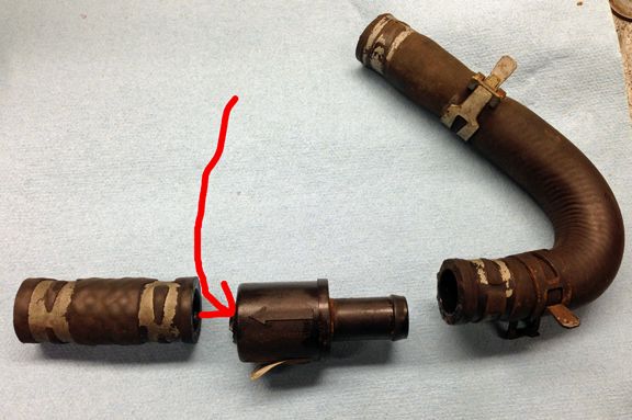
It may be a coincidence, but a few years ago a valve which looks like this: deteriorated to the point where the hoses had nothing to clamp on to. I removed the valve and hooked the hoses back up. I basically bypassed the valve. The valve, I believe, was inline with the top hose (image below)...
For user feedback reports, check out this Amazon site:
Bottom Line: The Dorman Product # 902-008 may not be identical in design internally, but it works as intended.5.0 out of 5 stars 2002 Dodge Grand Caravan 3.3l engine
Reviewed in the United States on April 6, 2022
Verified Purchase
This item works perfectly for me. I seen one review about arrow was backwards, not saying they are wrong but mine was correct. Amazon says it will not work on a 02 Grand Caravan 3.3l. I have posted a picture from manufacturer that it does. I have also posted 2 more pictures of all the other vehicles that this works on. Easy to install, took me about 20 minutes because I also replaced both hoses that connect to it.
Question:
Dear dorman, i need to know the in/out diameter for valve. it is possible to have a drawings for this component? let me know. regards. s barbera
Answer:
Sorry Dorman isn't permitted to release drawing of our products. There is an arrow molded into the side to show the direction of the flow.
By Technical Team MANUFACTURER on January 30, 2020
6,528 posts
·
Joined 2009
I wouldn't trust Dorman over my own observations. I once had a brand-new Dorman brake master cylinder fail to release my brakes, burning out my front brakes and toasting a hub. They are low quality replacement parts.
My vans have never had this restrictor valve. My 2004 with steel rear heater pipes doesn't, and my 2001 with aluminum pipes didn't. I think they are added on here and there when a customer complained, or maybe replacement assemblies came with them. My van has good heat without one, but I never use the rear heater because no one is back there.
My vans have never had this restrictor valve. My 2004 with steel rear heater pipes doesn't, and my 2001 with aluminum pipes didn't. I think they are added on here and there when a customer complained, or maybe replacement assemblies came with them. My van has good heat without one, but I never use the rear heater because no one is back there.
32,966 posts
·
Joined 2008
No, they were standard equipment on my 2002 DGC Sport with rear heat. Like with computer chips, they may have ran out every so often.
1,227 posts
·
Joined 2015
I'm not sure anyone knows when this valve is working or not... as Jeepman noted, replacing it with a hose may seem just as good, at least for the front-seaters!
If it's flowing heat to the driver when the valve is closed and the flow is low, then I'm pretty sure it's flowing heat to the driver when the flow is higher as well... regardless of whether the valve is opening up to reduce restriction at high flow or not. If valve doesn't open, then only real difference is a little more heat than usual goes to back, a little less heat than usual goes to the front, and more pressure than usual is generated at the restrictor.
As I understand it, the whole point of this valve is to keep the rear heater core from being starved at low coolant flow (low RPM), so a valve that never opens at high RPM/Flow will work just as well for that... unless you are capable of discerning the likely small delta in front/rear core heat exchange if the valve fails to open. All I can say is it's a good thing the body of the Dorman is fused if it's not opening correctly! And, hey, maybe that is why it is fused! I can see it now... "hey, our valve keeps blowing apart at high RPM!!! Well, we'll fix that... we'll just fuse the ends together! Drats... that still didn't work, now the nipples are tearing out! Well, ok so put some reinforcement ribs on each end cap to keep the plastic from stress fracturing... hey that works great now! Wonder why the OEM vavle doesn't have such issues???" Meanwhile, we're all really impressed at first... "wow, look how well built the Dorman part is... they fused the body together and added reinforcement ribs!!!" LOL!!!
FWIW, when I replaced the original leaking OEM valve, an interesting observation was that the restrictor plate "hole" was pretty much apparently worn open to the larger diameter of the seat/restristor-plate outer ring... resulting in a much larger hole and likely much less restriction than intended by design anyway, so these valves may long be pretty worthless well before they start leaking! And, nobody ever complained about a lack of heat coming from the rear vents... even if that was the case! Only got replaced when it began leaking... which I imagine to be the case for most folks.
As for front line technical support competence, I once asked KYB front-line technical support as to KYB's perspective for defining designations of "left" and "right" for the purposes of assuring correct placement of their struts on my vehicle as they intended. Just wanted to make sure we were both referencing it as viewed by the driver sitting in the driver seat while facing forward. Would have thought this sort of question would have been readily understood and easily answered by a company who designates product placement as left/right; however, after a couple of back and forth e-mails, my question had to be elevated to a higher level. To give credit where it's due, I did get a competent response once my question was elevated!
If it's flowing heat to the driver when the valve is closed and the flow is low, then I'm pretty sure it's flowing heat to the driver when the flow is higher as well... regardless of whether the valve is opening up to reduce restriction at high flow or not. If valve doesn't open, then only real difference is a little more heat than usual goes to back, a little less heat than usual goes to the front, and more pressure than usual is generated at the restrictor.
As I understand it, the whole point of this valve is to keep the rear heater core from being starved at low coolant flow (low RPM), so a valve that never opens at high RPM/Flow will work just as well for that... unless you are capable of discerning the likely small delta in front/rear core heat exchange if the valve fails to open. All I can say is it's a good thing the body of the Dorman is fused if it's not opening correctly! And, hey, maybe that is why it is fused! I can see it now... "hey, our valve keeps blowing apart at high RPM!!! Well, we'll fix that... we'll just fuse the ends together! Drats... that still didn't work, now the nipples are tearing out! Well, ok so put some reinforcement ribs on each end cap to keep the plastic from stress fracturing... hey that works great now! Wonder why the OEM vavle doesn't have such issues???"
Meanwhile, we're all really impressed at first... "wow, look how well built the Dorman part is... they fused the body together and added reinforcement ribs!!!" LOL!!!FWIW, when I replaced the original leaking OEM valve, an interesting observation was that the restrictor plate "hole" was pretty much apparently worn open to the larger diameter of the seat/restristor-plate outer ring... resulting in a much larger hole and likely much less restriction than intended by design anyway, so these valves may long be pretty worthless well before they start leaking! And, nobody ever complained about a lack of heat coming from the rear vents... even if that was the case! Only got replaced when it began leaking... which I imagine to be the case for most folks.
As for front line technical support competence, I once asked KYB front-line technical support as to KYB's perspective for defining designations of "left" and "right" for the purposes of assuring correct placement of their struts on my vehicle as they intended. Just wanted to make sure we were both referencing it as viewed by the driver sitting in the driver seat while facing forward. Would have thought this sort of question would have been readily understood and easily answered by a company who designates product placement as left/right; however, after a couple of back and forth e-mails, my question had to be elevated to a higher level. To give credit where it's due, I did get a competent response once my question was elevated!
1,192 posts
·
Joined 2018
One reason for a flow restrictor is to protect the heater core from high pressure generated by the water pump. I’ve heard that that pressure can be upwards of 40 psi. I don’t know if that’s why Chrysler did it, but there are other cars that have a flow restrictor for that reason.
The rear system may not need one because the long lines to the back would naturally restrict flow somewhat.
The rear system may not need one because the long lines to the back would naturally restrict flow somewhat.
6,528 posts
·
Joined 2009
Too much pressure wouldn't be the reason. The system runs at 16psi anyway, regulated by the radiator cap. Plus, there were tons of vans that didn't have the flow restrictor, and they worked fine. It seems to be an optional part.
What's crazy is why run the rear heater pipes on the outside of the van, losing heat? If they were so concerned with the rear heater core blowing hot, why didn't they simply insulate the lines? Did the restrictor really work so well that it cost less to utilize than insulating the rear heater lines? Just trying to figure out the logic the engineers were faced with. I know it's all about achieving X result in the most reliable and cheapest way.
What's crazy is why run the rear heater pipes on the outside of the van, losing heat? If they were so concerned with the rear heater core blowing hot, why didn't they simply insulate the lines? Did the restrictor really work so well that it cost less to utilize than insulating the rear heater lines? Just trying to figure out the logic the engineers were faced with. I know it's all about achieving X result in the most reliable and cheapest way.
1,192 posts
·
Joined 2018
Think about it — the water pump is pumping against the restriction of the thermostat and the two heater cores. If the pump’s flow capacity exceeds the flow of the restrictions the pressure will increase. Centrifugal pumps typically don’t produce a lot of pressure compared to a positive-displacement pump, but they certainly can create significant pressure. The radiator cap never sees that pressure, because the radiator is after the restriction of the thermostat.
There’s plenty of coolant flow to the rear heater. If the coolant cooled so much that It reduced heater performance they could just increase the size of the heater core. I doubt if there’s enough heat loss to really matter.
There’s plenty of coolant flow to the rear heater. If the coolant cooled so much that It reduced heater performance they could just increase the size of the heater core. I doubt if there’s enough heat loss to really matter.
1,192 posts
·
Joined 2018
This is interesting -- this is from the patent on the device (Unified Patents - Analytics Portal). It doesn't talk about pressure, but it talks about a high flow rate causing heater core erosion and damage.
It has also been found that the useful life of the heater core is substantially reduced if high coolant flow rates are allowed to proceed through the heater. The reason that the useful life is diminished at high flow rates is due to particles and other matter which are carried by the coolant. This matter may comprise normal residue left in the engine block coolant passages from the manufacturing process including sand left from the casting process and metal shavings left from the machining processes. These particles and other matter act as abrasives and abrade the inside of the passages in the heater core which are usually constructed of rather thin materials in order to promote heat exchange. At high fluid flow rates, this normal abrasion process can be greatly accelerated thus reducing the life of the heater.
As indicated above, high flow rates normally occur when the engine is turning at high RPM since the water pump is mechanically coupled to the engine. For this reason, many vehicle manufacturers place restrictions in the coolant lines feeding the heater to prevent or inhibit high fluid flow rates through the heater passages.
In the past, these restrictors operated satisfactorily to reduce the maximum flow rate of fluid through the heater at high engine speeds. However, these restrictors also restricted the flow at engine idle speeds. It has been found that in modern-day automobiles the amount of heat available in the coolant for heating the passenger compartment has been reduced. This reduction in heat availability is a result of using the coolant for other functions such as cooling turbochargers and other auxiliary equipment now forming part of modern automobiles. As a result, in vehicles that employ restricted coolant lines, insufficient heat is available for the heater when the engine is idling and unsatisfactory passenger compartment heating occurs on extremely cold days.
In many if not most vehicles, the coolant is circulated by an engine driven pump. Since the engine speed varies during vehicle operation, the flow rate of coolant in the heater circuit changes as well. Because the heat output of a heat exchanger is determined primarily by the temperature and flow rate of coolant through the exchanger, the heat output of the heater core also varies with engine speed. The output of the heater with the engine idling and the vehicle at a standstill is substantially less than the output of the heater with the engine turning at a substantially higher RPM, i.e., when the vehicle is traveling at highway speeds.
It has also been found that the useful life of the heater core is substantially reduced if high coolant flow rates are allowed to proceed through the heater. The reason that the useful life is diminished at high flow rates is due to particles and other matter which are carried by the coolant. This matter may comprise normal residue left in the engine block coolant passages from the manufacturing process including sand left from the casting process and metal shavings left from the machining processes. These particles and other matter act as abrasives and abrade the inside of the passages in the heater core which are usually constructed of rather thin materials in order to promote heat exchange. At high fluid flow rates, this normal abrasion process can be greatly accelerated thus reducing the life of the heater.
As indicated above, high flow rates normally occur when the engine is turning at high RPM since the water pump is mechanically coupled to the engine. For this reason, many vehicle manufacturers place restrictions in the coolant lines feeding the heater to prevent or inhibit high fluid flow rates through the heater passages.
In the past, these restrictors operated satisfactorily to reduce the maximum flow rate of fluid through the heater at high engine speeds. However, these restrictors also restricted the flow at engine idle speeds. It has been found that in modern-day automobiles the amount of heat available in the coolant for heating the passenger compartment has been reduced. This reduction in heat availability is a result of using the coolant for other functions such as cooling turbochargers and other auxiliary equipment now forming part of modern automobiles. As a result, in vehicles that employ restricted coolant lines, insufficient heat is available for the heater when the engine is idling and unsatisfactory passenger compartment heating occurs on extremely cold days.
6,528 posts
·
Joined 2009
That makes sense, especially since our vans don't use a water valve anymore to limit flow/heat - it circulates all the time. The abrasives in the coolant would act like a water jet over time.
2 posts
·
Joined 2022
Just had this fail today on my 2006 3.8L. The valve had become brittle and cracked at the base of the inlet. As a quick fix, I installed a Koehler 5/8in Heater Hose Connector Kit Part # H58 I picked up locally. Waiting for the OEM replacement 4677378AB from moparonlineparts.com to arrive. I did replace all of the OEM hose clamps with the screw type. I've never had good luck reusing OEM clamps.
2 posts
·
Joined 2022
Well, not sure if a fragment off of the restrictor valve was still in the system or just sheer dumb luck, but the water pump failed this morning and started leaking out of the weep hole. Got that replaced, wasn't too tough. Went ahead and replaced the alternator while I had everything apart since it has been groaning for a long time.
1 post
·
Joined 2023
Sir the valve was created as a recall to cure an over heating issue as well as a gurgling sound from the house that's verbatim from the dodge dealership so if installed backwards will definitely cause over heatingI'll probably need to see if I can find the old valves I have laying around to give a definitive answer. In a condensed version of my saga regarding replacing this valve long ago, I know that I figured out that the Dorman valve I purchased was configured backwards from the OEM and other manufacturer's replacement valves I went through on my adventure. Basically, there is a rubber grommet/oriface/seat inside the body of this valve with a spring holding it "closed" against one side of the valve body. Presumably, the coolant flow direction should act to compress the spring to increase flow around this grommet as pressure increases and the grommet/seal is pused back away from the valve body wall. IIRC, I used a pencil (eraser end) to play around with each valve and prove to myself that the Dorman valve was configured with the spring and valve seat (grommet thing) reversed as regards the arrow direction compared to every other valve I had. Though I like the "fused body" design of the Dorman, this shook my confidence enough that I ended up going with another manufacturer's part instead. If your Dorman valve is also designed "backwards" then it should go in the opposite direction of the OEM valve; however, I'd be concerned that they might have corrected the issue since then? IIRC, the OEM valve had the arrow installed pointing toward the firewall and the spring compressed in that same direction; however, I need to re-verify this. Would suggest seeing which way your Dorman valve compresses any maybe we can figure it out from there... This is unlikely to be the reason your van is over-heating... as I understand it, this valve purely serves to assist with getting heat to the rear of the van when the coolant flow/pressure is low...
5,048 posts
·
Joined 2017
Welcome to the forum
Your very first post and you are submitting useful information. We love members like you.
We look forward to reading more from you,
Cheers!
Your very first post and you are submitting useful information. We love members like you.
We look forward to reading more from you,
Cheers!
32,966 posts
·
Joined 2008
Just a flow control valve of sorts, the system will operate without it, later years didn't have it. Something to do with rear heat. GM and others use it too.
"Patent # 4800925
A two-stage flow controller for use in a vehicle heating circuit including a housing defining an inlet and an outlet and a flow control chamber disposed between the inlet and outlet. A spring biased flow controller is disposed for sliding movement within the chamber towards and away from a valve seat. The flow controller includes an annular segment defining a through aperture and a plurality of axially extending legs which support the segment for sliding movement within the chamber and in predetermined alignment with the valve seat. Projections are defined on a face of the annular segment. When the fluid flow exceeds a predetermined level, the projections initially engage a valve seat surface such that a variable orifice is formed by clearance regions between a confronting face of the element and the seat. The element deforms to diminish the clearance space between the face and the seat as a function of fluid flow rate. In a preferred embodiment, the housing includes two portions that are snapped together and are maintained in their assembled positions by a resilient retaining ring. Locking lugs are supported beyond an end surface of one of the portions by a plurality of arcuate tabs which together define a segmented groove having a diameter larger than an end bore defined by the portion. The other portion is sized to fit within the end bore and includes a groove for receiving the retaining ring when compressed. When the second portion is inserted into the bore, the retaining ring expands outwardly into the segmented groove to maintain the engagement between the two portions."
References:
 www.chryslerminivan.net
 www.chryslerminivan.net
The "rocket science":These type of restrictors are used for different reasons.
1) to cut down the coolant flow to keep the core from getting worn out by erosion. This is normally done on vehicles with large cooling systems with large pumps IE trucks.
2) to cut down on the noise of coolant rushing through the core.
3) to cut down on the flow to the front core so the rear core will get enough flow (balancing as was mentioned in an earlier post) if you have a rear heater.
Leaving your's out is unlikely going to cause you any trouble IMO.
"Patent # 4800925
A two-stage flow controller for use in a vehicle heating circuit including a housing defining an inlet and an outlet and a flow control chamber disposed between the inlet and outlet. A spring biased flow controller is disposed for sliding movement within the chamber towards and away from a valve seat. The flow controller includes an annular segment defining a through aperture and a plurality of axially extending legs which support the segment for sliding movement within the chamber and in predetermined alignment with the valve seat. Projections are defined on a face of the annular segment. When the fluid flow exceeds a predetermined level, the projections initially engage a valve seat surface such that a variable orifice is formed by clearance regions between a confronting face of the element and the seat. The element deforms to diminish the clearance space between the face and the seat as a function of fluid flow rate. In a preferred embodiment, the housing includes two portions that are snapped together and are maintained in their assembled positions by a resilient retaining ring. Locking lugs are supported beyond an end surface of one of the portions by a plurality of arcuate tabs which together define a segmented groove having a diameter larger than an end bore defined by the portion. The other portion is sized to fit within the end bore and includes a groove for receiving the retaining ring when compressed. When the second portion is inserted into the bore, the retaining ring expands outwardly into the segmented groove to maintain the engagement between the two portions."
References:
Mystery Part in Heating System - What to Do?
Today my better half was driving the DGC (204K miles)and called to tell me that there was steam coming from the hood. She said it wasn't overheating so I asked her to get it home. The coolant was a bit low and I have a pressure tester so I put about 16 PSI in the system. Sure enough, it was...
Variable Restrictor Valve Flow Direction?
I purchased a Dorman - OE Solutions - Variable Restrictor Valve (Part No. 902-008). There is an arrow on the part that is suppose to face firewall. There is controversy on which direction the valve is suppose to face. Many people are reporting the the arrow is incorrect. I no longer have my OEM...
1,227 posts
·
Joined 2015
Got a TSB number? Would like to see that one...Sir the valve was created as a recall to cure an over heating issue as well as a gurgling sound from the house that's verbatim from the dodge dealership so if installed backwards will definitely cause over heating
-
?
-
?
-
?
-
?
-
?
-
?
-
?
-
?
-
?
-
?
-
?
-
?
-
?
-
?
-
?
-
?
-
?
-
?
-
?
-
?
- posts
- 615K
- members
- 96K
- Since
- 2003
ChryslerMinivan.net is the best forum for Chrysler Town & Country, Dodge Caravan, Plymouth Voyager, and Chrysler Pacifica owners to discuss mileage, price, problems, towing and more. Join now!
Top Contributors this Month
View All
Mopar-Mofun
257 Replies
Jeepman
129 Replies
Long_Voyager94
103 Replies


